T.O.
1L-2A-1
|
|
ARMAMENT
EQUIPMENT.
DEFENSIVE
ARMAMENT.
Defensive
armament consists of either two M-16 or AR-15 rifles. On aircraft O-2, defensive
armament is located in mounts on the left cabin sidewall. The rifle mounts are
located over each center side window in aircraft 8 .
OFFENSIVE
ARMAMENT. 0
Offensive
armament consists of two armament pylons on the undersurface of each wing, a
non-computing optical gunsight directly in front of the pilot on the instrument
panel glare shield, an armament control panel located on top of the instrument
panel to the right of the gunsight, a trigger button on the pilot's control
wheel, and provisions for a strike or recon- naissance camera in the cabin floor
to the right of
1.
SUU-11A 7.62mm MinigunPod.
2. SUU-14/A Bomblet Dispenser (7 Tube).
3. MA-2/ A Rocket Launcher (2 Tube).
4. LAU-59/A Rocket Launcher (7 Tube).
ARMAMENT
CONTROL SYSTEM.
The
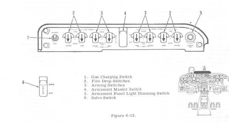
offensive armament controls are located on the instrument panel (figure 1-3),
armament control panel (figure 4-12), and on the underwing pylons (figure 4-14).
Electrical power for the armament control system is provided from the primary
bus bar.
Armament
Master Switch.
|
CAUTION The
armament master switch must be positioned OFF at all times except when
actually ready to activate the armament circuits. |
||
A
guarded armament master switch (4, figure 4-12) located in the center of the
armament control panel, is used to control armament operation. The switch is
marked MASTER and has two positions, ON and
Gun
Charging Switch.
The
gun charging switch (1, figure 4-12) is located at the left extremity of the
armament control panel and is marked CHARGE and OFF. When the charging switch is
in the CHARGE position, aircraft electrical power is provided to the battery of
the SUU- 11A Minigun Pod and furnishes battery charging voltage. The gun
charging switch should be placed in the CHARGE position as soon as after
take-off clean- up operations are completed to assure an adequate gun pod
battery charge.
Fire/Drop
Switch.
Four
fire/drop switches (2, figure 4-12}, one for
CAUTIONCaution
must be exercised to insure that the fire/drop switch is positioned in
accordance with the stores carried. |
Arming
Switch.
Four
arming switches (3, figure 4-12) one for each wing pylon, are located on the
armament control panel. The wing (RIGHT or LEFT) and pylon station on the wing (INBD
or OUTBD) is marked adjacent to each switch. Each arming switch is a
three-position switch and each switch detent is labeled. The switch detents are
NOSE, NOSE & TAIL, and OFF. The detent position selected will vary depending
upon the store carried on the affected pylon. The primary function of the arming
switches is to provide locking voltage to the arming lanyard shackles in order
that whenever bombs are dropped, the arming lanyards (nose or nose and tail)
will be retained in the shack- les allowing the bomb to fuse after separation
from the pylon.
Armament
Panel Light Dimming Switch.
The
light dimming switch is located at the right extremity of the armament control
panel and is marked LIGHTS DIM (5, figure 4-12). Rotation of the knob will
produce a corresponding increase or de- crease in armament control panel
illumination.
Salvo
Switch.
The
guarded emergency salvo switch (6, figure 4-12] is located on the pilot's
forward instrument panel directly above the altimeter and is marked SALVO on the
red switch cover. The salvo switch is a two- position switch and is always in
the OFF detent. When the switch guard is raised and the switch is placed in the
DROP detent, all external stores are released unarmed regardless of the selector
switch settings on the armament control panel.
The
trigger button (1, figure 1-13) is located on the left handle of the pilot's
control wheel. When the trigger button is depressed, firing voltage is
transmitted to the selected store which is released or fired.