|
|
T.O
1L-2A-1
CA-505
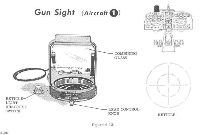
NON-COMPUTING OPTICAL GUNSIGHT.
The
CA-505 gun sight (figure 4-13) consists of an illuminated reticle and an optics
system composed of a Mangin mirror and adjustable combining glass to project the
reticle image to infinity. The combining glass angle is adjustable and will
provide a sight depression from 0 to 170 miliradian from the 0 mil reference
line.
Sight
Reticle.
The
CA-505 sight contains an etched metal reticle composed of an outer broken circle
with a diameter of 200 mils, an inner broken circle with a diameter of 100 mils,
and a center dot or pipper. The reticle is illuminated by three No.1968 quartz
iodide lamps which produce an illuminated reticle image (figure 4-13). The sight
has a red lamp located above the depression dial to provide illumination of the
dial setting.
The
combining glass angle is manually adjusted by the pilot by means of a knob
affixed to a graduated dial. The dial is integral with a circular cam which
actuates a plunger pin to adjust the combining glass angle. The amount of
depression angle selectable is limited only by the interference of the nose of
the aircraft with the line-of-sight of the pilot.
When
firing rockets or delivering other ordnance air to ground, the lead or
prediction angle of the air- craft with respect to the target is set at a
predetermined angle by means of the mil lead control knob (figure 4-13). The
prediction angle varies with the angle of dive, speed of the aircraft, and the
ballistics characteristic of the ordnance being delivered. The amount of lead or
sight depression angle is read from the index above the knob.
Gunsight
Reticle Light Rheostat Switch.
The dimmer switch (figure 4-13) located to the left of the gunsight on the instrument panel is a rheostat which controls the intensity of the reticle image. When the sight is not in use, the switch should be turned to DIM to prevent damage to the reticle bulbs in the event of yoltage surge. Turning the switch to BRIGHT increases reticle image intensity.