T. 0. lL-2A-l

EXTERNAL STORES.
External
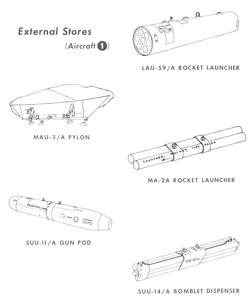
Stores Pylons.
Stores are suspended from four MAU-3A bomb racks housed in
non-jettisonable pylons, (figure 4-14), two under each wing. Each bomb rack
contains an electrical solenoid and mechanical linkage to open both rack hooks
and release the attached store which then free falls from the rack. The
suspension hooks are spaced 14 inches apart and the pylons are adaptable
to any external store equipped with 14-inch suspension lugs.
All stores carried by the pylon racks free-fall when either
the normal or emergency release systems are
SUU-11/A Minigun Pod.
The SUU-11/A aircraft gun pod (figure 4-14) is a self
contained GAU-28/A gun system of 7.62 mm which is adaptable to aircraft equipped
with bomb racks having the front and rear suspension hooks spaced 14 inches
apart. The main components of the pod are the front fairing assembly, ammunition
loader assembly, ammunition feeder assembly, recoil adapter assemblies, electric
drive assembly, rounds counter, spent cartridge ejector unit, rear fairing
assembly, battery and control assembly, support assembly, rounds counter drive
assembly, and drum assembly. The pod weighs approximately 245 pounds empty, 325
pounds loaded, is 85 inches long and is
SUU-14/A Bomblet Dispenser.
The SUU-14/A bomblet dispenser
(figure 4-14) has a triangular cross section formed by 6 tubes, each 73 inches
long and weighs approximately 50 pounds empty and 250 pounds when fully loaded.
The for- ward ends of the 6 tubes are covered with a blunt fairing assembly
which houses the firing mechanism used to eject the bomblets from the rear of
the tubes. The firing mechanism is composed of an electrical system, explosive
ejector cartridge, and ejector piston assembly. When release is intiatated, an
electrical current fires the ejector cartridge, the resultant expanding gasses
of which act against the piston assembly propelling both the piston assembly and
LAU-59/A Rocket Launcher.
The LAU-59/A is a reusable rocket launcher (figure 4-14)
capable of launching seven 2.75 inch FFARs (Folding Fin Aircraft Rockets) and
weighs approximately 5.15 pounds empty and 175 pounds fully loaded. The launcher
consists of three major components; a center section and a rear section which
may be used on repeated firings, and a forward frangible fairing which shatters
upon rocket firing. The center section contains the suspension system, metal launching
tubes with detents, and an intervalometer . The detent devices within the tubes
restrain the rockets against normal flight loads and provide electrical contact
to the rockets. Contacts on aft launcher bulkhead provide the rockets with a
ground in order that the firing circuits may be energized. Two receptacles on
top of the center section provide for connection to the aircraft firing
circuitry. Since the receptacles are wired in parallel, only one is utilized to
complete the launcher and aircraft circuits. As a safety requirement, the
receptacle not connected to the aircraft is fitted with a shorting but- ton
(attached to the receptacle dust cover) that grounds the launcher firing circuit
and prevents in- advertent operation of the launch intervalometer . The shorting
button is removed prior to take-off.
The built-in step type
intervalometer is designed for repeated firings, with a single or ripple fire
capa- bility depending upon the selector switch setting. If the selector switch
is set to RIPPLE, the pod
MA-2/ A Rocket Launcher.
The MA-2A rocket launcher (figure 4-14) is com- posed of two launching tubes, and a suspension sys- tem. The launcher is connected to the aircraft's firing circuits and is fired by the pilot depressing the trigger button. One rocket will fire each time the trigger button is depressed.