T.O. 1L-2A-1

KB-18
STRIKE CAMERA.
The
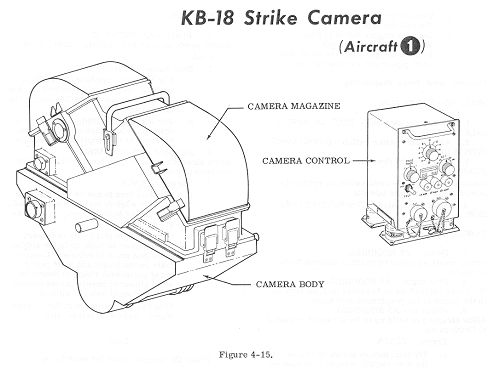
KB-18 strike camera (see figure 4-15) is of the moving film, panoramic type used
for daylight low- level photography. It is mounted in the vertical position on
the cabin floor to the right of the pilot, and provides fore and aft
photographic coverage of 180 o along the line of flight and 40 o laterally. The
major components of the camera system are the camera body, magazine, and camera
control. The camera operates on 28-volts DC through a circuit breaker on the
pilot's circuit breaker panel.
Camera
Body.
The
camera body contains a double-dove rotary prism, lens, automatic exposure
control and motor , feedback potentiometer, variable slit width and diaphragm,
and the scan drive motor and its associated gear mechanism. The camera body
supports the magazine and provides the linkage gear which couples the drive
mechanism to the magazine for film drive. Three trunnions enable the camera body
to be rigidly mounted within the aircraft.
The
magazine is a light-tight container and provides chambers for the film supply
and take-up spools.
Camera
Control.
The
camera control contains switches and electronic components necessary for
operating the camera system. The switches determine camera operating time,
cycling rate and film exposure, and are pre- set on the ground. The camera is
ready for operation when a remotely-located camera power switch is positioned
ON, and operates when a camera run switch button is depressed. The camera will
continue to operate after the camera button is released for the overrun time
(2-32 seconds) preset on the camera control OVERRUN switch.
The
camera power switch (5, figure 1-6) is a two- position toggle switch labeled ON
and OFF. Placing the switch in the ON position provides electrical power to the
camera control.
Camera
Run Switch.
The
camera run switch (4, figure 1-6) is a spring- loaded switch labeled CAMERA and
ON. Depressing the button provides starting voltage to the camera. When the
button is released, the camera will continue to operate for the preset overrun
time as deter- mined by the switch setting on the camera control.
Film
Out light.
The film out light (3, figure 1-6) is an amber light which illuminates when the last of the film is exposed. The light is marked FILM OUT .